
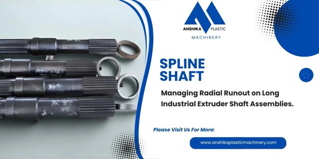
In high-torque parallel twin-screw extruders, the drive transmission relies heavily on the absolute straightness and precision of the internal drive shafts. Because these assemblies span significant lengths to accommodate multiple modular processing zones, even microscopic deviations in straightness can magnify exponentially toward the discharge end.
Radial runout—the degree to which a rotating shaft deviates from its true geometric axis—is one of the most destructive mechanical issues on an extrusion line. Left unchecked, it causes uneven flight wear, excessive vibration, and premature failure of internal components.
1. What Causes Radial Runout in Extrusion Lines?
Shaft deflection and runout rarely happen overnight; they are typically the result of cumulative mechanical stress, thermal cycling, or installation errors.
Extreme Torsional Overloads: Sudden torque spikes, hard contaminant jams, or uncalibrated electrical surges place massive twisting forces on the central spline shaft, introducing permanent micro-bends into the metal.
Thermal Expansion Mismatches: During high-temperature compounding, uneven heating along the length of the segment barrel can create localized thermal gradients that stress internal components unevenly.
Improper Assembly and Torque: Failing to torque coupling bolts evenly or forcing mismatched modular components onto the shaft can induce slight angular bending right from installation.
2. The Operational Impact of Shaft Deflection
When a shaft exhibits radial runout, it alters the precise working clearances required for efficient compounding.
Metal-on-Metal Contact: As the shaft rotates off-center, the outer edges of the mounted screw elements and kneading elements will continuously scrape against the inner walls of the barrel, generating severe frictional heat and metal shavings.
Accelerated Spline Wear: Misalignment places uneven pressure on the splined connection points between the gearbox and the drive shafts, causing rapid fretting corrosion and spline stripping.
To safeguard your drive line against premature fatigue, ensure your equipment utilizes high-strength, precision-machined Twin Extruder Components engineered to handle rigorous industrial torque loads.
3. How to Measure and Monitor Shaft Runout
Catching runout early prevents catastrophic mechanical damage to your entire processing assembly.
Use Precision Dial Indicators: During scheduled maintenance when the internal screws are extracted, mount a magnetic base dial indicator (indicator clock) directly onto the bare spline shaft at multiple points along its length.
Slow Manual Rotation: Slowly turn the drive mechanism by hand and record total indicator reading (TIR) measurements to identify exactly where maximum deflection occurs.
Compare Against Manufacturer Tolerances: Consult original equipment specifications to ensure measured runout stays well within safe operating limits before reinstalling your conveying elements.
4. Best Practices for Prevention and Alignment
Verify Drive Train Alignment: Routinely check that the motor, gearbox output, and internal shafts maintain absolute coaxial alignment during major maintenance shutdowns.
Avoid Shock Loading: Prevent hard foreign objects from entering the feed throat by utilizing inline magnetic separators and strict feedstock inspection protocols.
Inspect During Every Screw Pull: Make shaft runout checks a mandatory step every time you pull the screws for cleaning or wear evaluation.
For rugged, precision-crafted assemblies built to maintain strict geometric tolerances under heavy continuous workloads, explore our complete catalog of Screw Elements.
