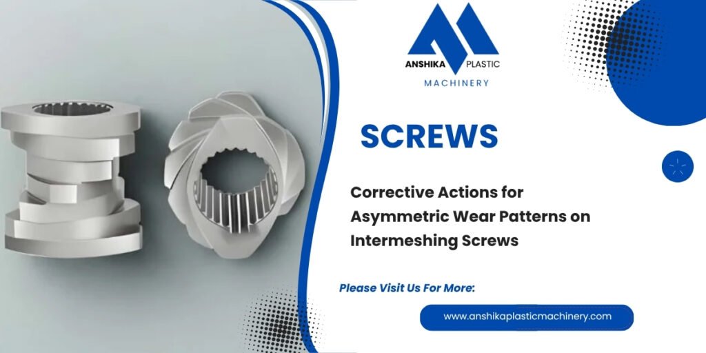
In an ideal extrusion environment, internal components experience uniform, gradual wear across all flight surfaces over thousands of operational hours. However, plant engineers frequently pull screws during routine maintenance only to discover severe, uneven degradation concentrated on just one side of the flight profile.
This asymmetric wear compromises the precise gap clearances required for self-cleaning, leading to material dead zones, reduced throughput, and declining product quality. Identifying the root cause of this uneven wear is essential before installing replacement parts.
1. Root Causes of Asymmetric Flight Wear
Asymmetric wear does not happen randomly; it is a mechanical symptom of directional forces acting disproportionately on the rotating assembly.
-
Lateral Force Disbalance: In high-speed compounding operations, the pushing flanks of co-rotating screw elements absorb the majority of the mechanical load. If torque distribution is uneven, one screw bears more stress than its counterpart.
-
Micro-Deflections in the Drive Line: If the central spline shaft experiences micro-bending or torsional deflection under extreme torque loads, the rotational axis shifts slightly, causing the flight tips to rub continuously against one side of the segment barrel wall.
-
Feed Asymmetry: If feedstock enters the feed throat unevenly or packs toward one side of the channel, the initial conveying zones experience lateral loading that propagates down the entire length of the screw.
2. The Operational Impact of Uneven Wear
When flight tips wear down asymmetrically, the critical intermeshing clearance gaps are thrown out of specification.
-
Loss of Self-Cleaning Efficiency: The tight wiping action between adjacent screws depends on uniform geometry. Uneven wear creates wide gaps where polymer can slip backward unmixed.
-
Accelerated Localized Friction: Once material begins bypassing the worn flanks, it experiences localized high-shear friction, speeding up thermal breakdown and metal degradation.
3. Corrective Actions and Engineering Solutions
Fixing asymmetric wear requires more than simply swapping out damaged parts; it demands a thorough system audit.
-
Check Drive Alignment and Shaft Straightness: Use precision dial indicators to measure your spline shaft assembly for runout or angular misalignment before mounting new components.
-
Replace Affected Modular Segments: Because your machine utilizes a modular design, you do not need to replace the entire screw assembly. You can isolate and replace only the worn individual screw elements or kneading elements that show critical thickness loss.
To restore your line’s volumetric efficiency and maintain tight processing tolerances, equip your machine with high-durability replacement Screw Elements engineered for exact dimensional matching.
4. Preventive Strategies for Longevity
-
Optimize Upstream Feed Distribution: Ensure your feeder is centered properly over the feed throat to distribute material evenly across both screws.
-
Monitor Operating Torque: Keep historical logs of motor amperage and torque output to catch mechanical binding or shaft deflection early.
-
Inspect During Every Scheduled Pull: Document wear measurements during routine maintenance to track whether wear is uniform or shifting toward one side.
For heavy-duty industrial applications requiring maximum resistance against abrasive and asymmetrical loads, explore our complete range of precision-crafted Twin Extruder Components.
